
HTB Low Logic (challenge)
Published:
A writeup of the Hack The Box challenge “Low Logic” with very easy difficulty
Low Logic (very easy)
CATEGORY: Hardware
CHALLENGE DESCRIPTION:
I have this simple chip, I want you to understand how it’s works and then give me the output.
The zip file contains a chip.jpg and a input.csv
in0,in1,in2,in3
1,0,0,1
1,1,0,0
0,1,1,0
0,0,1,0
1,1,0,1
1,0,0,1
0,0,0,0
0,0,1,0
0,0,0,0
0,1,1,1
0,0,0,0
1,1,1,1
0,0,1,0
1,0,1,1
1,0,0,0
0,0,0,0
0,0,1,0
0,1,1,1
0,1,1,0
1,0,0,1
0,0,1,0
1,0,0,1
1,1,0,0
0,0,1,0
0,0,0,1
1,1,0,0
0,1,1,1
0,0,1,1
1,1,0,1
0,1,0,0
1,1,0,0
0,1,1,1
0,1,0,1
0,0,0,0
1,1,1,1
0,0,1,1
1,0,0,1
1,1,1,0
1,0,0,1
1,0,0,0
1,0,0,0
1,1,0,0
1,0,0,0
1,1,0,0
0,1,1,1
0,0,1,1
1,1,1,1
1,0,1,1
0,0,0,1
1,1,0,0
0,0,0,1
0,1,0,0
0,1,0,1
0,0,1,1
0,0,1,1
0,1,1,1
0,1,0,1
0,1,0,1
1,1,1,0
1,0,1,1
0,1,0,0
1,0,0,0
0,0,0,0
1,0,0,0
0,1,1,0
0,1,0,0
0,1,1,1
0,0,1,1
1,0,1,0
0,1,1,0
0,0,1,0
0,0,0,0
1,0,1,0
0,1,1,1
0,1,1,1
0,1,1,0
0,0,0,0
1,1,1,0
0,1,0,1
0,0,0,1
0,1,0,1
1,1,1,0
1,0,0,1
1,1,1,1
1,1,0,0
1,1,1,1
0,0,1,1
1,1,1,1
1,0,0,0
1,1,1,1
0,1,0,1
0,1,1,0
0,0,1,0
1,0,0,0
1,1,1,1
1,0,1,1
1,0,0,1
1,0,1,1
1,1,1,1
0,0,0,1
1,1,1,1
1,1,0,1
0,0,0,0
1,1,0,1
0,1,0,1
0,1,0,1
1,1,0,0
1,0,1,1
0,1,0,0
0,1,0,1
0,1,1,0
1,0,1,0
0,0,1,0
0,0,1,0
0,1,1,1
1,0,1,1
1,0,1,0
1,1,0,0
1,0,0,1
1,1,0,0
0,1,1,0
1,0,1,1
1,0,0,1
0,0,1,1
1,1,1,1
1,1,0,0
1,1,1,1
1,1,0,1
0,0,0,1
0,1,0,1
0,0,1,1
1,1,1,1
1,0,0,0
0,1,0,0
0,1,1,1
1,0,1,1
0,1,0,1
1,1,0,0
1,0,1,1
1,1,0,0
1,1,1,1
0,0,1,0
0,1,0,1
1,0,0,0
0,1,0,0
0,1,0,0
1,0,1,1
1,1,1,1
0,1,1,0
1,1,0,1
1,0,1,0
0,0,1,0
0,0,0,0
1,1,0,1
1,1,0,0
0,1,1,0
1,0,1,1
1,1,1,1
0,0,0,0
0,1,1,1
1,0,0,0
1,1,0,1
1,1,0,1
1,1,1,1
0,0,0,1
0,1,0,1
0,1,1,0
0,0,0,1
0,1,0,1
0,0,1,1
1,1,0,1
1,0,0,0
1,1,1,1
1,1,0,0
0,1,0,0
0,0,1,0
1,0,0,0
0,1,1,0
1,1,0,1
1,1,0,1
1,0,0,1
0,1,0,1
1,1,0,1
1,0,1,1
1,0,0,0
1,1,0,1
1,1,1,1
1,1,0,0
1,1,0,0
1,1,0,0
1,0,0,0
0,1,1,1
So I’m new at the hardware area so here we go:
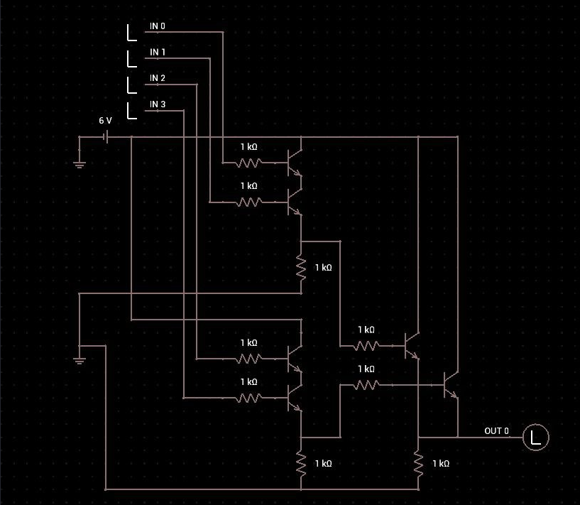
The image shows 4 input circuits (IN0-IN3) and a Light (L) as output (OUT0).
All the inputs are connected to resistors and vertical switches.
There are multiple AND’s with resistors that connect to a OR.
The lamp only lights when a certain combination of specific switches are closed.
So the OUT0 is 1 (on) when 1 of the following logical conditions are true:
in0 = 1 AND in1 = 0 AND in2 = 0 AND in3 = 1in0 = 1 AND in1 = 1 AND in2 = 0 AND in3 = 0in1 = 1 AND in2 = 1 AND in3 = 1in0 = 1 AND in1 = 1 AND in2 = 0 AND in3 = 1
We can save time writing a python script:
import csv

def process_logic_operations(input_file):
# Initiate a list to save the results
  results = []

  # Open input.csv and skip the header
  with open(input_file, mode='r') as infile:
    csvreader = csv.reader(infile)
    next(csvreader)

    # Read input from input.csv and convert to integers (0 or 1)
    for row in csvreader:
        input1 = int(row[0])
        input2 = int(row[1])
        input3 = int(row[2])
        input4 = int(row[3])

        and_output1 = input1 & input2 # First AND operation
        and_output2 = input3 & input4 # Second AND operation

        final_output = and_output1 | and_output2 # Final OR operation

        results.append(str(final_output)) # save results as string

    return ''.join(results) # Join everything together in a binary string
# Execute the script and print the results
input_file = 'input.csv'
output = process_logic_operations(input_file)

print(output)
The output after running the script:
010010000101010001000010011110110011010001011111010001110011000000110000011001000101111101000011011011010011000000110101010111110011001101111000001101000110110101110000011011000011001101111101
But this isn’t a flag so let’s convert this binary to ACSII using cyberchef: